Careful study of many of the proposed definitions and vague descriptions of Computer Integrated Manufacturing (CIM) has led to the following definition of CIM for the context of this thesis.
This definition is as follows:
CIM is the application of computer technology to integrate the functions (eg. order receipt, planning, design, production, shipment) of a manufacturing enterprise. CIM results in automation of the information flow and provides direct or indirect interfaces to the physical and human resources of the enterprise.
Although CIM is the commonly used term for such a system, it may be more precisely called a Computer Integrated Enterprise (CIE) [Hodges 1988, 9], [CIO 1989, 16].
Other definitions of CIM from various literature sources are as follows:
"CIM means many things to many people." "On the shop floor, CIM means work cells and DNC." [Martin 1988, 36]
Savolainen calls this a "narrow CIM definition." A definition of CIM as automated production - Computer Numerical Control (CNC), Direct Numerical Control (DNC), Robotics, etc. - ignores the benefits of integrating production to the other manufacturing functions. "The narrow definitions of CIM are already outdated and misleading compared to the common use of the concept CIM." [Savolainen 1988, 5]
Another definition of CIM is "... fusing information and manufacturing technologies together, by integrating and completely automating the manufacturing process, and by linking the factory floor to the strategic planning, marketing, finance, distribution and purchasing functions." [Alter 1989, 14] The key requirement for CIM according to this definition is "completely automating the manufacturing process." Automation can be a by-product of CIM, but it is not a requirement. Also, if a definition lists functions to be integrated, then product design and others should be included.
Alter later expands the definition of CIM to include "the harnessing of all information necessary to correctly produce a product..." Information "is the common thread of getting things done." [Alter 1989, 16]
Although this is not a complete definition of CIM, there is general agreement that "information" is the key to integration.
Colgate reported that "... Robotics is a very narrow part of CIM..." [Colgate, 1988, 88]
For some types of manufacturing, automation and robotics can be a significant part of the CIM system but for other non-automated industries, like apparel manufacturing, CIM can be implemented without automation or robotics and still provide increased benefits to the company.
"CIM involves the use of computers for the integration of the various operations of an apparel enterprise." "Computer Aided Manufacturing (CAM) entails the effective utilization of computer technology in the management, control, and operations of the manufacturing facility through direct or indirect computer interface with a company's physical and human resources." [Jayaraman 1989]
Use of the word "involves" makes the definition safe, but incomplete. The definition itself even implies that the use of computers for integration is not all that CIM involves. The definition of CAM mentions "through direct or indirect computer interface with a company's physical and human resources." This should be part of a CIM definition, but should not be a requirement for CAM.
"CIM utilizes computer technology for management, control, and operation of a manufacturing facility by interfacing with both the physical and human manufacturing resources of a company." [USL A-CIM 1989, E-1]
This definition is basically the same as the CAM definition mentioned previously and supports the notion that it is more a definition of CIM than CAM. The two important points are "utilizes computer technology" and "interfacing with both the physical and human manufacturing resources."
A report by Harland Hodges describes CIM in the following way: "The concept of computer integrated manufacturing embodies the desire to automate the factory by encompassing all phases of manufacturing from planning and design to manufacture and shipment. Its goal is to optimize the benefits of automation for the particular needs of the company." [Hodges 1988, 11-12]
Hodges also mentions that "the obvious solution is to automate the interfaces." And that "the full efficiencies of computers are not realized due to the manual, ineffective interfaces." [Hodges 1988, 9]
He then puts it in a nutshell by quoting: "The computer is incredibly fast, accurate and stupid. People are unbelievably slow, inaccurate and brilliant. The marriage of the two is a force beyond calculation." [Hodges 1988, 13]
An article in Computers in Industry contains a very detailed definition of CIM. The article defines CIM in four ways:
The third definition is the most useful in the context of this thesis: "CIM is the integrated form of CAD/CAM and business functions. The ideal CIM system applies computer technology to all of the operational functions and information processing functions in manufacturing from order receipt, through design and production, to product shipment. The integrated computer systems in CIM assist, augment, and/or automate the operations. Full implementation of CIM results in automation of the information flow through every aspect of the company's organization." [Savolainen 1988, 5]
Finally a computer science textbook definition of CIM: "CIM is a concept, not a technology. It is a management philosophy what all of the technologies must work together. CIM is a way of looking at the firm's production resource as a single system and defining, funding, managing, and coordinating all improvement projects in terms of how they affect the entire system. CIM is a systems view of production rather than molecular view of only dealing with the parts separately." [McLeod 1986, 618]
This definition is not specific enough to be of much practical use in the Apparel Manufacturing Industry.
Most of the CIM definitions address the subject of information flow in manufacturing. The key to CIM is having the necessary information readily available through a computer. This thesis provides an example of how the information can be made available more automatically.
This section describes some of the tools and methodologies available for designing and implementing CIM systems.
To design a CIM system for a company, or for that matter even to decide whether a company needs a CIM system, one must first make a detailed analysis of the company. This type of study is often referred to as the Systems Analysis (ie, examination, identification, and evaluation of the components and the interrelationships involved in systems) [Shemer 1987, 509], [Wang 1988, 17], [Jayaraman 1988, 7] or the Systems Engineering Method for CIM systems planning. [Bravoco 22]
One part of such an analysis process is the construction of models of the company [Bravoco 22]. These models are commonly referred to as the architecture [Jayaraman 1988, 1989], [Zachman 1987]. The architecture serves as a blueprint for implementing CIM [Jayaraman 1988, 1].
During the process of constructing detailed models of a company, one gains several types of knowledge: [Jayaraman 1989, 2], [Bravoco 23]
Following are lists of some of the different types of models available. [Zathman 1987, 285]
The following techniques describe data and/or information:
The following are process descriptions:
These final models are network descriptions:
Some other techniques used by systems analysis and data processing professionals are: [Jayaraman 1988, 7]
Most of these well-known tools and techniques are geared toward the data processing industry and only a few of them may be considered for use in the manufacturing industry. This is because they do not explicitly address the issues of control and mechanisms inherent in manufacturing operations. [Jayaraman 1988, 7]
One modeling methodology that is particularly useful for studying a manufacturing industry is IDEF [Jayaraman 1988, 14], [Young 1989].
The USAF established the Integrated Computer-Aided Manufacturing (ICAM) program in the 1970s with the objective of increasing manufacturing productivity through the systematic application of computer technology. From this program emerged the IDEF (ICAM Definition) method which included two modeling methodologies which graphically characterize manufacturing: IDEF0, the Function Modeling Technique and IDEF1, the Information Modeling Technique. [Jayaraman 1988, 9]
IDEF is intended as a means of discovering what actually does happen within the entire manufacturing enterprise and communicating this understanding. It also provides an effective base line understanding (AS IS model) from which improvements are suggested (TO BE model). [Bravoco]
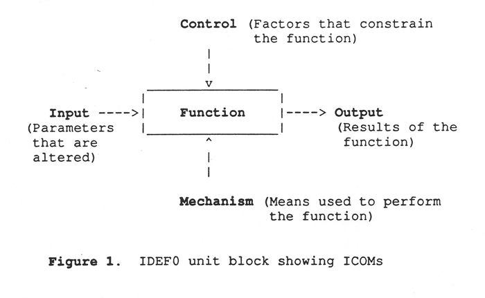
IDEF0: The function Model, identical to SofTech's Structured Analysis and Design Technique (SADT) [Ross 1985, 31], provides a description of manufacturing in terms of a hierarchy of functions and information that flows between functions. It establishes a structure for gathering data aimed at understanding the manufacturing environment to the desired degree of detail. Each function is represented in a box and the Inputs, Controls, Outputs, and Mechanisms (ICOMs) associated with the function are drawn as arrows (see Figure 1). Thus, a well structured IDEF0 model provides organization, clarity and standardization for a graphical representation of the various functions in an organization it serves as the basis for the next stage of the architecture development process. [Jayaraman 1988, 9]
IDEF1: The IDEF1 methodology, developed by Hughes Aircraft, specifically addresses the logical structure of shared information, defining this structure in terms of entities, attributes of entities, and relationships among the entities. This information modeling process is fundamental to the development and management of the enterprise database(s). It also speeds database implementation and provides for more stable and flexible databases. [Appleton 1986, 66]
The IDEF1 technique guides users through the development of information models, which lead to precise, normalized, graphical statements of meanings and structure. These information models represent the business rules of an organization or system. The models, and their associated business rules, facilitate communication and support identification of information requirements. Additionally, the information models can be translated info physical database structures for implementation by any database management system. [Appleton 1986, 66]
Dr. Sundaresan Jayaraman is currently developing a set of IDEF models that will represent the Apparel Manufacturing Architecture (AMA). [Jayaraman 1989]
The Apparel Manufacturing Architecture (AMA) is a set of IDEF models for pants, being developed at the Georgia Tech/Southern Tech Apparel Manufacturing Technology Center (AMTC). The work is being carried out under a research grant from the U.S. Defense Logistics Agency. The primary researchers are Dr. Sundaresan Jayaraman and Mr. Rajeev Malhotra, PhD student.
In its efforts to become more competitive, the Textile/apparel industry is concentrating on adopting hi-tech concepts such as CIM. An important prerequisite for the successful implementation of CIM in the apparel industry is a detailed knowledge and understanding of the functions and information flows associated with the manufacturing process. Such a definition of the manufacturing process is known as an architecture of manufacturing.
To integrate the functions of a manufacturing enterprise, communications standards for software and hardware must be established. Several research efforts and their recommendations are described below.
(Manufacturing Automation Protocol and Technical Office Protocol)
MAP started as General Motors' (GM's) attempt to standardize communications methodology so that its more than 40,000 intelligent devices scattered across 14 plants could intercommunicate. The effort was initiated in April 1980 by a GM task force, drawing from the work of five organizations, including the INternational Standards Organization (ISO), the American National Standards Institute (ANSI), the Computer and Business Equipment Manufacturers Organization (CBEMA), the Institute of Electrical and Electronic Engineers (IEEE), and the National Bureau of Standards (NBS). The MAP document, Version 2.1, was comprised of a selection of available communications standard protocols and GM specifications covering topics for which no standards existed. [Brooks 1986,72]
TOP protocol suite was developed, as a companion to MAP, to support office automation. [USL A-CIM 1989, 20] It was initiated by Boeing for use in technical office environments. [Brooks 1986, 78]
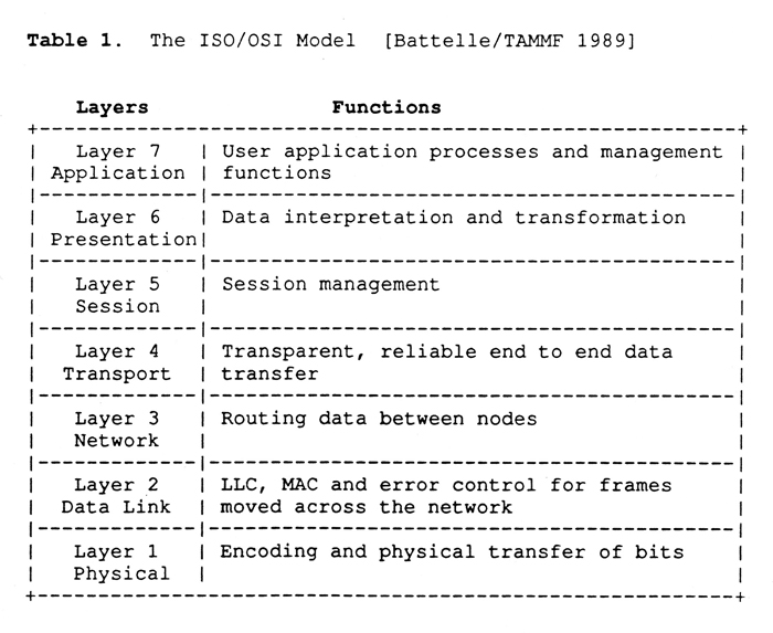
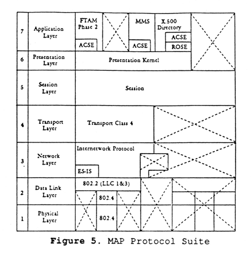
In 1984, GM and other leading U.S. companies formed the MAP users group (now the MAP/TOP users group). Both MAP and TOP support the seven layers (see Table 1) of the International Standards Organization / Open Systems Interconnection (OSI/ISO). [USL A-CIM 1989, E-2]
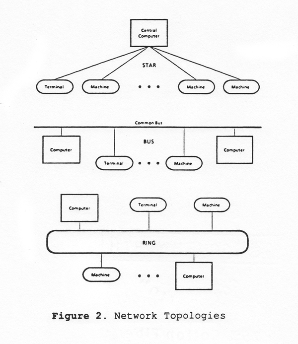
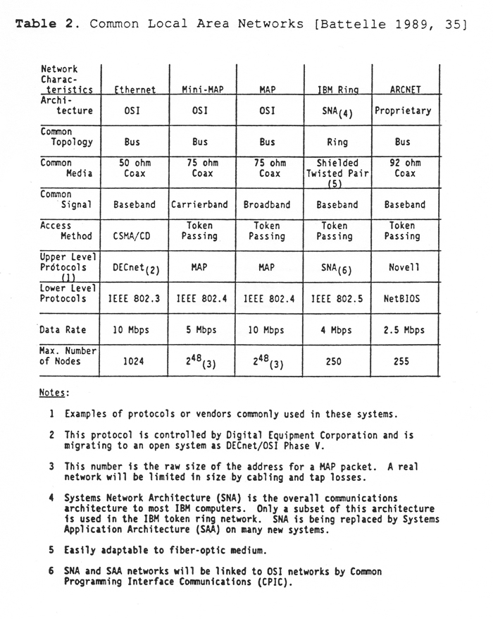
The MAP and TOP protocol suites are quite similar, but their protocol suites remain separate and there are differences. One difference is that MAP includes direct support for manufacturing through use of the Manufacturing Message Specification (MMS), at layer 7, while TOP concentrates on office automation services. Also, MAP limits the physical network to just one option; the IEEE 802.4 Token Bus, while TOP supports IEEE 802.3 "Ethernet" and IEEE 802.5 Token Ring (see Figure 2 and Table 2 ). [USL A-CIM 1989, E-3]
Textile and Apparel Machinery Modernization Foundation's Factory Floor Computer Communications Standards Assessment for the Textile and Apparel Industry. [Battelle 1989]
This study was commissioned to assess factory floor communications networking in the U.S. textile and apparel industry, and determine if applicable standards exist which could facilitate CIM.
Current communications industry standards and both proprietary and open networking schemes were reviewed, but none of these standards were complete. There is hope that computer industry standards may be complete by the early or mid-1990s.
Computer industry giants have accepted the Open Systems Interconnection (OSI) model (Table 1). The OSI model and supporting specifications are evolving rapidly and will provide the basis for industry specific standards.
To help complete the standards specifications, the report suggests that apparel producers in conjunction with their equipment manufacturers should:
Pertinent to apparel producers is Digital Equipment Corporation's decision to fully support OSI, and International Business Machines Corporation's (IBM) decision to accommodate OSI. Hewlett-Packard, Honeywell Bull, Data General, and other vendors also provide OSI products and a foundation for integrated systems. [Battelle 1989, 25]
Until a complete set of standards is developed, apparel producers should develop internal networking schemes adhering to OSI specifications. Those choosing DEC-based systems should consider migrating to Enterprise Management Architecture, Common Management Information Protocol, the Institute of Electrical and Electronic Engineers (IEEE) 802.3 specification, and other OSI compliant specifications. Producers choosing IBM based systems should press for Common Programming Interface Communications, Systems Application Architecture, IEEE 802.5 and other specifications and products which facilitate the OSI model. [Battelle 1989, 40]
(Fully Integrated Garment Manufacture)
FIGARMA was presented by Nilas T. Nilsson in the 1982 Apparel Research Conference Proceedings as a visualization of how apparel manufacturing in the 90s would develop from the state-of-the-art that existed in the early 80s. Nilsson described FIGARMA as a flexible automation development strategy where the integrated data processing network could be compared to a "ferry line" linking various distributed "islands of automation". [ARC 1982]
Using and extending the concepts of MRP (Manufacturing Resource Planning) and FMS (Flexible Manufacturing Systems) into an application of CIM in the form of distributed assembly automation, Nilsson constructed a conceptual model of an integrated, highly automated and flexible, garments assembly plant based on distributed microprocessors controlled by data networks. [Nilsson, 2-3]
The long-range FIGARMA program did not aim at achieving fully automated and unmanned garment assembly. Mr. Nilsson conceived a network-controlled assembly line of production cells which would have auto-adaptive properties. The R&D focused on the study and development of the functions of such production cells which would utilize a new type of highly flexible and inter-changeable manual/auto workstations as a building block. [Nilsson, 2-3]
The assembly manufacturing flow would be triggered and guided by the fabric parts which would carry their own identification, positioning/mateing, sewing and routing instructions in computer-readable form to the auto-adaptive microprocessor/sensor system modules controlling the operations at each workstation and the material flow between them. [Nilsson, 2-3]
The production cells would be linked together in assembly lines which would be controlled by a multi-layer of integrated data networks which would conceivably incorporate the total information flow of the company - and also incorporate outside linkages to suppliers and direct linkages to the home of the consumer. [Assem. Aut. in ...]
Nilsson summarized his FIGARMA strategy in a diagram (Figure 3). A study of the FIGARMA diagram shows that it contains the familiar components and elements inherent in the old are of apparel manufacture as well as integration concepts that were completely new to apparel manufacturing in the early 1980s. [ARC 1982]
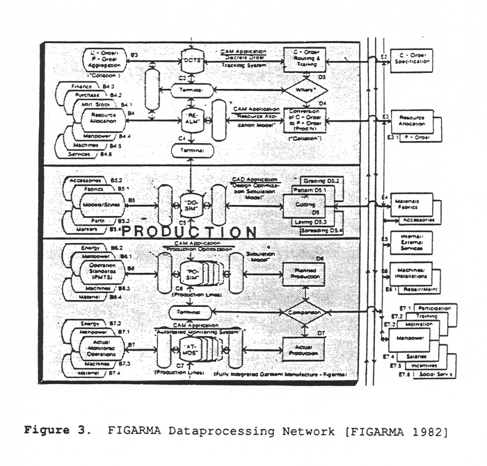
The upper part of the diagram covers Order Planning and Resource Allocation procedures performed by the software packages indicated in the center line of the network. These centerpieces of the FIGARMA distributed data processing network which have names like:
represent the "ganglia of the spinal cord" of the information flow. The databases used by these software packages are indicated to the left of the diagram; some key input elements and some of the operations involved are indicated to the right. [ARC 1982]
The central part of the diagram covers the automated and integrated CAD operations, Integrated Design and Cutting Operations, which are integrated with the CAM operations. The lower part covers the Production Line Operations. [ARC 1982]
All pertinent customer, style, material, manufacturing and shipping data regarding a specific production order are stored - right from the beginning and only once - in the various databases of the plant computer network as illustrated in (Figure 3).
FIGARMA, through intricate interactions among databases, software packages, and other elements of the plant computer network, would provide on-line control and monitoring of the production flow of each individual line and of all the lines of the plant. The FIGARMA concept was far superior to what could be achieved by the computerized manufacturing support systems of the early 1980s, according to Nilsson. [ARC 1982]
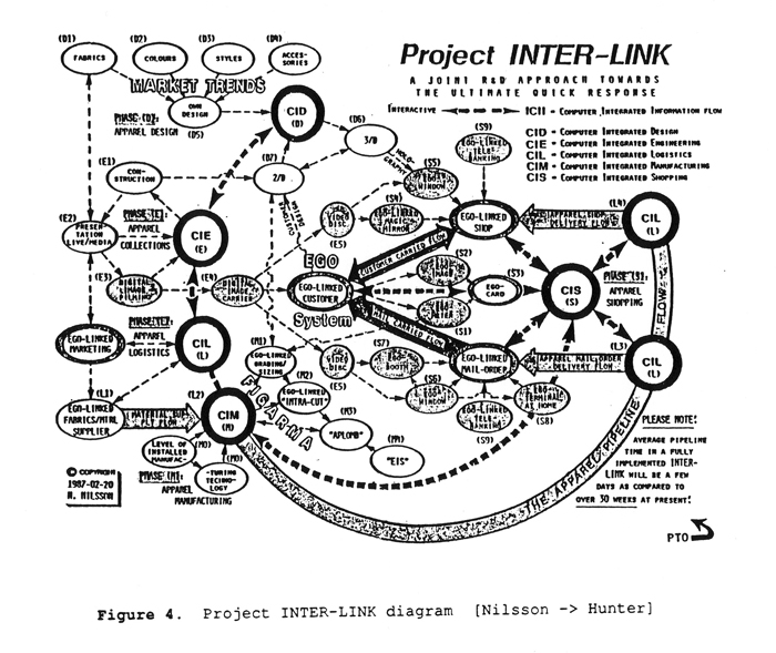
The FIGARMA concept has been considerably extended since its first presentation. [Chalmers 1983, 5] It has now become an integral piece of project INTER-LINK; what Nilsson refers to as "A Joint R&D Approach towards the Ultimate Quick Response." [Nilsson 1987]
Project INTER-LINK is a step-by-step application towards linking the various areas of computer integrated operations in the apparel pipeline. [Nilsson 1987] The Process INTER-LINK by means of ISDN (see Figure 4) links all of the processes in the apparel pipeline, from the design/creation of collections through the manufacture/distribution of apparel by means of computerized logistics control, to the delivery of apparel made-to-measure by means of consumer-pulled informatics. [Nilsson 1988]
(Apparel Manufacturing Protocol Suite)
The American Apparel Manufacturers Association (AAMA) and the University of Southwestern Louisiana (USL) jointly established the USL Apparel CIM (A-CIM) Center in 1988. AMP is the CIM protocol suite recommended by the USL A-CIM Center for the U.S. apparel industry.
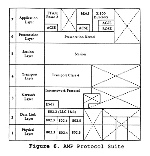
AMP is a CIM protocol suite that extends MAP (Figure 5) with the addition of IEEE 802.3 "Ethernet" and IEEE 802.5 Token Ring as network hardware options (see Figure 6).
This recommended network conforms to the ISO/OSI Model (Table 1), supports MMS and allows existing networks to be integrated. It also provides a potentially lower cost implementation than MAP since one may use the Ethernet or Token Ring (see Figure 2 and Table 2 ) network hardware options. [USL A-CIM]
(Textile Apparel Linkage Council) [TALC 1989]
Formed in May 1986, TALC is an all-volunteer organization consisting of apparel textile suppliers, apparel manufacturers, academic, and industry members. Two of TALC's main objectives are:
Through the work of TALC's Electronic Data Interchange (EDI) committee, EDI conventions to ANSI X12 are available for interindustry adoption.
TALC's other standards cover the following: [TALC 1989]
[Savolainen 1988, 17]
CIMGLUE is Savolainen's suggestion for a general tool to build software package interfaces. Tapani Savolainen is a systems engineer in industrial automation for Hewlett-Packard and a CIM-consultant.
There is a huge amount of software packages to be used as building blocks to CIM applications, but they are programmed to work together only in rare cases. Interfacing two packages is not a trivial task, even if one produces an ASCII-file and the other can accept an ASCII-file as input.
Savolainen proposes that this kind of problem could be approached by using the techniques of language compilers combined with knowledge based systems and an interactive user interface. He suggests that a tool could be built that would produce the runtime format conversion system between almost any software packages using ASCII files (or corresponding system buffers) as input and output.
After prompting the user with pop-up menus and examples, CIMGLUE could obtain the relations in the syntax and semantics between the output and input files, it could then generate a runtime program or rule base to be used in the conversion.
Savolainen theorizes that the approach to build CIMGLUE depends on the constraints selected to the applications package category and file contents. Possible ways to approach the problem include:
It is conceivable that you could integrate a system with what Michael Galane, senior manufacturing consultant, Manufacturing Systems Group, Hewlett-Packard Co. (Cupertino, CA), calls "sneakernet": people hustling through your facility carrying information and wearing Reeboks. [Huber 1987, 44]
This strategy does not deal as much with computers as with information. It takes the 'C' out of CIM and leaves you with Information Integrated Manufacturing (IIM).
A manufacturing environment needs dynamic (changing) databases which have interconnections between different pieces of information. Traditional databases (like hierarchical and network) could not meet these needs satisfactorily, so IBM's Dr. E. F. Codd invented the Relational Database. [Young notes]
It is called "Relational" because Dr. Codd was a mathematician and decided to use the term "relation" to describe what we call a "table." The original paper was titled "A Relational Model of Data for Large Shared Data Banks." The name stuck and now Table-Based Management Systems are called Relational Database Management Systems (RDBMSs). [Young notes]
Some of the features of Relational Databases are:
REBMSs will most likely be used as the medium of common storage and retrieval of information in a CIM system. Descriptions of several projects relating to RDBMSs follow:
Multibase is a prototype software system that provides a uniform, integrated interface, which allows the user to reference data in distributed, pre-existing, heterogeneous databases with one query language over one database description. Practical applications of the prototype are being made at General Dynamics and at Rockwell International. The project is being conducted by Computer Corp. of America (CCA), Cambridge, MA, and is jointly supported by DARPA and the U.S. Navy. [Appleton 1986, 64]
(Integrated Information Support System)
IISS is a software system that achieves control of, and access to information in pre-existing, distributed, heterogeneous databases to allow data shareability and to provide a means for improving data quality and data timeliness. Practical applications of this technology are being made by Boeing and McDonnell Douglas Aircraft Co. IISS research is being conducted by Boeing, DACOM, SDRC, and CDC, under contract with the U.S. Air Force at Wright-Patterson Air Force Base in Dayton, OH. [Appleton 1986, 64] It was initiated by the ICAM program office.
(Integrated Manufacturing Distributed Database Administration)
IMDAS is a prototype software system that provides update and retrieval services over pre-existing, distributed, heterogeneous files and databases. The project is being sponsored as part of the National Institute of Science and Technology (NIST) (formerly National Bureau of Standards) Advanced Manufacturing Research Facility and is being conducted by NIST (Gaithersburg, MD) and the University of Florida. [Appleton 1986, 64]
(Integrated Design Support)
The IDS project is chartered to assemble various off-the-shelf tools and to add technology as required to support the management and control, update and retrieval, of existing and future technical data for the B-1B aircraft. These technical data are distributed in heterogeneous databases. The technical project is being conducted by Rockwell, DACOM, SDRC, and CCA, for the USAF at Wright-Patterson base in Dayton, OH. [Appleton 1986, 64]
With recent developments in hardware and software, several companies have been able to implement what they consider to be CIM systems, but the textile apparel manufacturing industry is not yet a leader in CIM.
Traditionally, manufacturing processes which lend themselves to automation have been prime targets for CIM. Indeed, numerically controlled (NC) and robotic systems were even thought of as CIM several years ago. Once a process is automated, the next logical step is to integrate it with other manufacturing operations.
Companies manufacturing high cost items and companies manufacturing items to a high degree of accuracy with very well defined manufacturing specifications lead the list of CIM success stories. Automobile and computer manufacturers are two examples.
Automation was the driving force behind CIM in most industries, but since apparel manufacturing is difficult to automate, other forms of computerization might have to pave the way to CIM. Two angles currently under development that might help led to CIM are production monitoring systems and CAD systems.
Below are three examples of companies with "CIM" systems. GM's Truck & Bus group is one of the industry pioneers in CIM. Pirelli General is the most completely integrated example. And (TC)2 is an example of some of the CIM technology that is currently available to the apparel manufacturing industry.
Two of the "ultimate" plants, in terms of CIM (for 1987), were unveiled when General Motors (GM) opened the Truck & Bus plants in Pontiac, MI and Fort Wayne, IN.
Despite the fact that the plants both displayed many examples of new automated machinery, a trip through either plant would leave the uninformed missing the point. The main event here is transparent ... even invisible. It is a totally integrated, multiple-level, multiple-vendor electronics communication and control network based on the General Motors' Manufacturing Automation Protocol (MAP).
As Ernest O. Vahala, director, Manufacturing Engineering Operations, GM Truck & Bus Group explains: "MAP is the backbone of a totally computer-integrated manufacturing system."
"The total integration of the manufacturing systems is being controlled by a strategy that requires a bi-directional data flow with varying time requirements at each level of the distributed architecture. The decision support level is a remote corporate processing center. The system-support level is the resident plant host. The area-manager level provides supervisory control for its respective area. The cell-controller level provides the integration of the devices within its domain. The lowest level consists of the individual device control that actually make the equipment function."
Supporting computer systems assist in the plant operation, including monitoring and controlling the facility supporting devices, maintaining maintenance records, monitoring fire control devices, recording employee attendance, and providing central library services for programmable-device programs.
The two plants are now in full production (1987). Vahala explains the system's operation as follows: "We have about 80 broadcast devices out in the assembly plant. First of all, the orders that come in from dealers get broken into details and then get blown up to the IBM 4381 mainframe that we have in each of the plants. Then the information goes down to the VAX 8600s that function as area managers."
"The download from those 8600s then shoots out to about 80 devices including HP cell controllers and other cell and unit controllers. Those devices are in the areas of the plant where you start your schedule build-up simultaneously. And that goes on all the time, instead of at the beginning of a day or of a shift. The 'utility', which is the MAP network, is both critical and transparent to the plant floor. So the utility is the key to scheduling and planning, because every one of those 80 points depends on the next decision for the next product component subassembly on what comes to it. Production scheduling is a millisecond thing that goes on every second of every 16 hours a day that we run."
There is substantial fringe benefit to the system. There are 24 cells in the Pontiac East plant (25 at Ft. Wayne). Each of those cells manages its own area. If there are problems in a cell, the system queries the controllers. When downtime develops, the programmable controller raises the flag, the cell control makes the inquiry, and the signal is sent to the maintenance center, where it appears on the screen and tells the person the existing problem. There is no need to pick up a history report the next morning to see what happened. The information is available real time with downtime being measured in minutes instead of hours.
[Mullins, 1989]
Pirelli General is one of the world's major manufacturers of electrical cables, and building wires for a substantial proportion of the total cable market - approaching 200 million a year in the UK alone.
These products are relatively low-tech, and the market is crowded with fierce competition. To remain competitive, it became clear to Pirelli General that a totally new business approach was needed ... to reduce labor content, reduce material use and waste, and reduce the work-in-progress, while all the time maintaining quality standards.
Pirelli's latest plant in Aberdare, South Wales has a comprehensive CIM system. According to Stanley Crooks, Pirelli General's chairperson, the project is very much a "pathfinder," a prototype for the whole Pirelli group.
"We believe the new Aberdare plant will prove a model for similar factories in the future," he notes emphatically. "That being the case, there is a significant element of R&D in the cost which we have identified and treated as such. Nevertheless, it is still a working plant designed to keep us a jump ahead of international competition."
Pirelli took two main partners in the project: the Italian industrial automation specialist SEIAF S.P.A and IBM UK (which supplied all the computer systems for the plant). The overall system developed by the three companies links computer systems at machine level to computer systems at process zone and plant levels.
The electronic linkage operates on a "token ring" system carried on a Pirelli fiber-optic network. The idea of this is to obviate electromagnetic interference with communications - a more-than-likely possibility with conventional wiring.
At the top of the computer pyramid is the business management system, which handles customer orders. These enter the system either directly or through the external telephone network connecting Pirelli's regional distribution branches. Orders are passed to the manufacturing management system which controls product data, inventory, production scheduling, materials acquisition, production control, technical data analysis, costing, purchasing and maintenance.
Data from this level is fed to the next one down the pyramid: the Plant Operating Management System (POMS). This is the heart of the system because it manages all aspects of shop floor planning - sequencing of machines, inventory management, control of all automated guided vehicles, performance monitoring and quality control.
Finally, at the base of the pyramid is the process control system, managing and monitoring the basic functions of the equipment and the machine Computer Numerical Controlled (CNC) systems themselves.
POMS continuously controls the plant processes and sequences the production minute by minute. Real-time data from all company resources - availability of materials, machine status, employee skill levels, work-in-progress, and inventory management parameter - is used to select the job each machine does next and the sequence of movements of material around the production zones.
The control for the various layers of the pyramid described above is hierarchical. At the top is an IBM System 36 handling business management, then IBM PCs handling manufacturing systems, while individual machine controls are the responsibility of GSC's GAM 80 and similar CNC systems.
Many of the machines have been modified to enable them to change rapidly from one type of wire to another - for example, to permit color changes at full running speed without wastage during the changeover.
Throughout the plant, all machinery has been designed to interface mechanically and automatically with the Automatic Guided Vehicle (AGV) system. Due to its control by POMS, the AGV system becomes an integral part of the production process. Linked to the controlling computers and the FMS, the AGVs allow the factory to function with a planning horizon of just a few minutes. The system itself notes deficiencies, generates missions, selects routes and performs other essential functions to ensure smooth continuous production.
(Textile/Clothing Technology Corporation)
(TC)2 is a research/demonstration facility for apparel manufacturing utilizing some of the latest developments in apparel manufacturing technology.
By my definition (TC)2 does not have an actual CIM system, but it does have several systems that use computers to integrate the information of a few functions. I shall call these systems "islands of CIM."
(TC)2 has four main "islands of CIM":
The CAD system is by Microdynamics. It operates on a platform of two PCs (an IBM PS/2 Model 60 and an IBM PS/2 Model 70 386 ). The CAD system is integrated with a plotter and a Gerber cutter via cable connections.
Garment pattern pieces are designed on the CAD system and then markers are
generated using the combined intelligence of the designer and the computer.
(A
The marker data follow two paths:
The real time production monitoring system is by Leadtec. This system runs on an IBM System 36 minicomputer. The cut garment pieces are given a bar-coded bundle coupon and are then tracked in real-time through the production operations.
As each operation is performed on the garment, the sewing specialist communicates with the Leadtec system via bar-code readers or keypads mounted at each work station. Leadtec keeps statistics on time, operator efficiencies, progress of bundles, etc.
The Unit Production System is by Eton Systems, Inc. It runs on a PC platform (Compaq Deskpro 386s) and consists of 12 workstations and a computer-controlled overhead conveyor system which transports the work in process (WIP) between the stations in an 'intelligent' dynamic manner.
The conveyor system tracks the WIP by workstation as hangers pass bar-code readers. Each workstation also has a keypad for additional communications to the system.
The UPS system produces real-time computer screen reports on production, hanger route history, and line balance. Also, end-of-day reports on wages, performance and skill, quality, etc.
The PC network uses an Arcnet Configuration and Novell Netware. The network is set up in a modified star topology (Figure 7). At the center of this system is a file server with a hard disk. Connected to the file server are several 'hubs', and up to 16 PCs can be connected to each hub.

The programs and data on the hard disk are available to all the PCs connected to the network Several applications are maintained on the file server including: activity scheduling, inventory, catalog, Work-Aid (requests for maintenance), telephone/address directory, parking permit data, and word-processing.
In the near future (TC)2 plans to try out a package by Apparel Computer Systems (ACS) which will put much of the manufacturing data including CAD, UPS, real-time monitoring and administrative databasing into one common database system. The ACS package will run on a mini-computer platform. This would be a large step towards CIM since it is using a computer to integrate so many functions and automate their information flow.
Since CIM has the potential to "step on toes in the worst way" [CIO 1989, 28], this type of project must be managed in a very careful manner. The following are some general tips for successfully implementing a CIM system:
Get senior management involved. [CIO 1989, 22] CIM projects need a "champion", someone with the authority to make something happen and the guts to take a risk. The reason for this is that it is often difficult to justify a CIM system using traditional accounting procedures; someone needs to be behind the CIM project who has enough authority to say "Despite the low calculated ROI, I know that this is something we have to do." [Huber 1986, 55]
Make a bold commitment at the design stage; there are no inexpensive solutions to CIM. [Mullins 1986, 49] To help hold a CIM project on course and within budget, develop a clear target for CIM in the form of strategic objectives; and then only technology required to meet strategic objectives should be invested in. [Battelle 20]
CIM, by automating the information flow between the processes, makes it even more necessary that the basics of the operations be correct. [CIO 1989, 18] Start with a thorough understanding of the strengths and weaknesses of the current system and then correct the manufacturing problems, do not try to automate around them. [Battelle 20] Especially, do not automate a process that is not understood, or one that is overly complex. [Huber 1987, 44]
Develop a functional system model and implementation plan from the top-down, but implement from the bottom-up. [Battelle 21] The model can help save money by catching mistakes in the design rather than the manufacturing stage. [CIO 1989, 22]
Frequently, the biggest problem is getting the users of the system "up to speed" in operating, maintaining, and getting the most out of their new investment. [Martin 1988, 39] Plan for people integration by promoting personnel involvement and training along the development process. [Battelle 21]